🏠 Home → Equipment → 1-WIRE Ex
¶ Device Description
The autonomous ROSSMA IIOT-AMS 1-Wire Ex switch with 1-Wire digital temperature sensor is designed for temperature measurement with subsequent wireless data transmission. The device is developed for use in hazardous areas at industrial facilities, utilities, and hard-to-reach locations. The switch enables installation of measuring instruments in places without power sources and operates in harsh climatic and weather conditions.
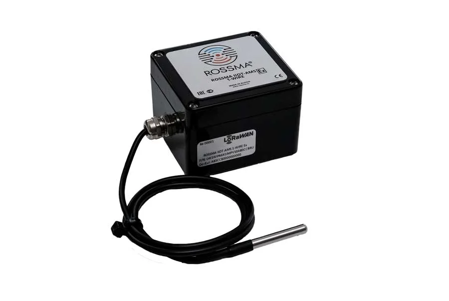
Fig. ROSSMA IIOT-AMS 1-WIRE Ex meter-switch appearance
Compatible sensors:
- Temperature sensors with 1-Wire digital interface (DS18B20, DS18S20 and analogs)
Equipment is registered in the register of the Ministry of Industry and Trade of the Russian Federation as equipment manufactured on the territory of the Russian Federation (Conclusion 48859/11 dated June 11, 2021).
¶ Technical Specifications
- Connection interface: 1-Wire (Dallas Semiconductor digital protocol)
- Number of inputs: 1 digital 1-Wire input
- Battery type: 14 A/h; 28 A/h; 126 A/h
- Transmission interval/14 A/h battery life: 1 min/90 days, 2 min/180 days, 10 min/300 days, 1 hour/3 years 150 days, 24 hours/10 years
- Operating temperature range: -55…+85°C
- Built-in temperature sensor: no (external 1-Wire sensors used)
- LoRaWAN device class: A
- LoRaWAN activation: OTAA/ABP (configurable), ABP — default
- Antenna type: internal
- Transmitter power: 25 mW (configurable)
- Receiver sensitivity: -138 dBm
- Supply voltage: built-in 3.6 V battery, 14 A/h capacity, D size
- Battery voltage measurement: yes (sent with each transmission)
- Housing dimensions: 80×75×55 mm
- Mounting: directly to sensor, cable ties to support, DIN rail, wall mount
- Radio range: up to 5 km in urban areas; up to 15 km in rural areas
¶ Capabilities
- 1 digital 1-Wire input for temperature sensor connection
- Configurable measurement interval from 1 time/min
- On-demand measurement by command
- Cascade connection of multiple sensors on one bus (up to 10 devices)
- Automatic sensor identification by unique ROM code
- High measurement accuracy (±0.5°C for DS18B20)
¶ Functional Features
The meter-switch is a Class A device (LoRaWAN® classification) providing the following functionality:
Network capabilities:
- ADR support (Adaptive Data Rate) — automatic data rate adaptation
- Configurable activation type: OTAA / ABP (default: ABP)
- Frequency plan: EU-868 / RU-868 (default: RU-868)
- Confirmed packet transmission support (configurable)
Operating parameters:
- Transmission interval: from 1 min and above (remotely configurable via LoRaWAN®)
- Default value: 1 time per hour
- Number of inputs: 1 (one 1-Wire digital input)
- Battery capacity: 14000 mAh — designed for 40,000 data packets ± 10%
Recommendation: Do not set intervals less than 1 minute to ensure long autonomous operation.
¶ 1-Wire Protocol
1-Wire (One-Wire) — a serial communication protocol developed by Dallas Semiconductor (now Maxim Integrated). Protocol features:
1-Wire advantages:
- Only 2 wires: data + ground (power can be supplied via data line)
- Each sensor has a unique 64-bit ROM code
- Multiple devices can be connected to one bus
- Range up to 100 meters with proper topology
- Low power consumption
Supported sensors:
- DS18B20 — digital temperature sensor (-55°C...+125°C, accuracy ±0.5°C)
- DS18S20 — DS18B20 predecessor (9-bit resolution)
- DS1822 — DS18B20 analog with simplified functionality
¶ Contacts and Connection
¶ Switch Contact Description
ROSSMA IIOT-AMS 1-WIRE Ex has the following contacts for sensor connection:
| Contact | Function | Description |
|---|---|---|
| DQ | Data (1-Wire) | 1-Wire data line (bidirectional) |
| GND | Ground | Common wire (ground) |
| VCC | Power +3.3V | Power for 1-Wire sensors |
Maximum parameters:
- Sensor power voltage: 3.3V
- Maximum VCC current: 50 mA
- Number of sensors on bus: up to 10
- DQ line length: up to 100 meters
IMPORTANT: Use a 4.7 kOhm pull-up resistor between DQ and VCC when connecting multiple sensors or when line length exceeds 10 meters.
¶ Connecting 1-Wire Sensors
¶ Connection Diagram
Single sensor connection topology:
┌─────────────────┐
│ ROSSMA 1-WIRE   │
│                 │
│  DQ  ──────────────── DQ (Data) — DS18B20
│                 │
│  GND ──────────────── GND (Ground) — DS18B20
│                 │
│  VCC ──────────────── VDD (Power) — DS18B20
└─────────────────┘
Multiple sensor connection topology:
┌─────────────────┐
│ ROSSMA 1-WIRE   │
│                 │
│  DQ  ────┬───────── DQ (sensor 1)
│          │
│          ├───────── DQ (sensor 2)
│          │
│          └───────── DQ (sensor 3)
│                 │
│  GND ────┬───────── GND (all sensors)
│                 │
│  VCC ────┬───────── VDD (all sensors)
└─────────────────┘
IMPORTANT: When connecting multiple sensors, a 4.7 kOhm pull-up resistor between DQ and VCC is required.
¶ DS18B20 Sensor Pinout
Standard TO-92 package (bottom view, pins facing you):
  ___
 /   \
|  O  |  — top view
 \___/
  | | |
  1 2 3

1 — GND (ground, black)
2 — DQ (data, yellow)
3 — VDD (power +3.3V, red)
¶ Cable Requirements
Recommended cable:
- Twisted pair (UTP Cat5 or higher)
- Shielded cable for industrial conditions
- Maximum line length: 100 meters (at 15.4 kbps)
- Cross-section: 0.5-0.75 mm²
¶ Application Examples
¶ Temperature Monitoring in Refrigeration Chambers
Task: Temperature control in freezer chambers at warehouse
Equipment:
- ROSSMA IIOT-AMS 1-WIRE Ex
- DS18B20 sensor in sealed housing
Data for transmission:
- Chamber temperature (°C)
- Battery charge
- Communication status
Frequency: every 10 minutes
¶ Pipeline Temperature Control
Task: Temperature monitoring on oil/gas pipeline
Equipment:
- ROSSMA IIOT-AMS 1-WIRE Ex
- 5× DS18B20 sensors at different pipeline sections
Data:
- Temperature at 5 points
- Anomaly detection
- Freezing warning
¶ Transformer Substation Temperature Monitoring
Task: Power transformer temperature control
Equipment:
- ROSSMA IIOT-AMS 1-WIRE Ex
- 3× DS18B20 sensors (top, middle, bottom of transformer)
Data:
- Winding temperature
- Oil temperature
- Transformer overheating
¶ Additional Information
- Device Installation — installation instructions
- Battery Replacement — battery replacement
- Protocols and Commands — control commands and data formats
- ROSSMA Configurator — device configuration
- Troubleshooting — diagnostics and problem solving
¶ Related Pages
Software:
- ROSSMA Configurator — transmission interval settings, sensor identification
- ROSSMA NETS Server — telemetry viewing, device management
- Data Decoder — 1-WIRE device payload analysis
Technical Documentation:
- Exchange Protocols — 1-WIRE device packet format
- LoRaWAN Technology — RU864 frequency plan, device classes
- Quick Start — first network connection
- Battery Life Calculator — battery life calculation
Other Devices:
- ANALOG Single Channel — for 4-20 mA sensors
- MODBUS — for Modbus RTU devices
- PULSE — for pulse sensors
- Device Catalog — all ROSSMA IIoT-AMS models