🏠 Home → Equipment → ANALOG Single Channel
¶ Device Description
ROSSMA IIOT-AMS ANALOG meter-switch is designed for data acquisition from monitoring and measuring instruments with current interface 4…20 mA and/or 4…20 mA+HART and/or resistive interface such as pt1000, Ni1000, TK5000, with subsequent wireless data transmission. It can be used at industrial facilities, housing and communal services infrastructure, and in hard-to-reach locations. The meter-switch enables installation of monitoring instruments in places without power supply and operates in harsh climatic and weather conditions.

Depending on configuration, devices are equipped with a built-in 3.6 V battery with capacity of 14 Ah, or built-in battery packs with 3.6 V voltage and capacity of 28 Ah or 126 Ah. Simultaneously, the meter-switch can be powered from an external DC source with voltage from 3.3 V.
WARNING: Meter-switches are equipped with non-rechargeable lithium-thionyl chloride (LiSOCl2) battery ER34615M/T manufactured by Fanso. Attempts to charge the battery may cause fire!
ROSSMA IIOT-AMS ANALOG is equipped with one analog input, or one analog input with HART protocol support, or four analog inputs.
¶ Device Modifications
Single Channel:
- ROSSMA IIOT-AMS ANALOG Single channel
- ROSSMA IIOT-AMS ANALOG Ex Single channel (explosion-proof)
- ROSSMA IIOT-AMS ANALOG Ex Single channel 28 Ah (compact increased capacity)
- ROSSMA IIOT-AMS ANALOG Ex Single channel 126 Ah (increased capacity)
Four-Channel (X4):
- ROSSMA IIOT-AMS ANALOG X4
- ROSSMA IIOT-AMS ANALOG X4 PWR (with 220V power)
- ROSSMA IIOT-AMS ANALOG Ex X4 (explosion-proof)
- ROSSMA IIOT-AMS ANALOG Ex X4 126 Ah
- ROSSMA IIOT-AMS ANALOG Ex X4 (DC 3.3V)
Explosion-proof modifications (Ex) have explosion protection marking 1Ex e IIC T4 Gb X / 1Ex db IIC T5 Gb X and are designed for operation in hazardous areas according to GOST R 31610.0-2014. Protection degree IP66.
¶ Operating Principle
The meter-switch supports two operating modes:
¶ ✅ Working with Active Instruments
Operating with monitoring and measuring instruments powered by an external power source.
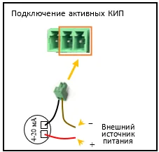
Figure 1. Connecting active control and measuring instruments to ROSSMA IIOT-AMS ANALOG X1
¶ ✅ Working with Passive Instruments
Operating with monitoring and measuring instruments powered by the meter-switch's built-in battery.
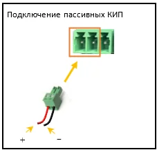
Figure 2. Connecting passive control and measuring instruments to ROSSMA IIOT-AMS ANALOG X1
¶ Operating Algorithm:
- Data is read from the monitoring instrument with a configurable period starting from 30 seconds. Data is stored in meter-switch memory and transmitted during scheduled wireless sessions at set intervals.
- Data transmission period can be configured from 30 seconds. By default, manufacturer sets data transmission interval to once every 15 minutes. Data transmission is performed by a timer set in the meter-switch's internal memory.
- Meter-switch communication timing management is performed via network server and can be adjusted by command.
¶ Technical Specifications
¶ General characteristics:
- Connection interface: 4-20 mA current loop or resistive pt1000, Ni1000, TK5000; HART.
- Operating temperature range t,°C: -55…+85
- Built-in temperature sensor: yes (sent with every connection)
- Antenna type: internal
- Built-in battery charge measurement: yes (sent with every connection)
- Mounting: directly to sensor, with cable ties to support, on DIN rail, wall-mounted
Power type: Built-in 3.6 V battery, capacity 14 A/h, D size
Battery life:
| Transmission interval | Service life |
|---|---|
| 1 min | ~90 days |
| 2 min | ~180 days |
| 10 min | ~300 days |
| 1 hour | ~3 years 150 days |
| 24 hours (once per day) | ~10 years |
Housing dimensions: 80×75×55 mm
Application: Standard operating conditions, frequent data transmission
Maximum number of packets: 40,000 ± 10%
Power type: Built-in 3.6 V battery pack, capacity 28 A/h
Battery life:
| Transmission interval | Service life |
|---|---|
| 1 min | ~180 days |
| 2 min | ~360 days |
| 10 min | ~2 years |
| 1 hour | ~10 years* |
| 24 hours (once per day) | ~10 years* |
Housing dimensions: 80×75×55 mm
Application: Compact solution with extended battery life
Maximum number of packets: 80,000 ± 10%
Modifications:
- ROSSMA IIOT-AMS ANALOG Ex Single channel 28 Ah
Power type: Built-in 3.6 V battery pack, capacity 126 A/h
Battery life:
| Transmission interval | Service life |
|---|---|
| 1 min | ~2 years |
| 2 min | ~4 years |
| 10 min | ~7 years |
| 1 hour | ~10 years* |
| 24 hours (once per day) | ~10 years* |
Housing dimensions: 260×160×90 mm
Application: Hard-to-reach locations, rare battery replacement
Maximum number of packets: 360,000 ± 10%
Modifications:
- ROSSMA IIOT-AMS ANALOG Ex Single channel 126 Ah
- ROSSMA IIOT-AMS ANALOG Ex X4 126 Ah
Power type: External DC source from 3.3 V
Service life: Unlimited (depends on power source)
Housing dimensions: 80×75×55 mm
Application: Sites with available power supply, continuous operation
Modifications:
- ROSSMA IIOT-AMS ANALOG Ex X4 (DC 3.3V)
* Maximum service life of lithium-thionyl chloride batteries is limited to 10 years due to natural self-discharge, regardless of capacity.
¶ LoRaWAN Technical Specifications:
- Device class in LoRaWAN network: A
- Activation in LoRaWAN network: OTAA/ABP (configurable), ABP – default
- Transmitter output power: up to 100 mW (configurable), default 25 mW
- Sensitivity: -138 dBm
- Radio communication range: up to 5 km in urban areas; up to 15 km in rural areas.
- Frequency plan: EU-868/RU-868 (configurable)
¶ NB-IoT Technical Specifications:
- Exchange speed: 25/20 kbps (single-tone) or 60 kbps (multi-tone) (DL/UL)
- Radio frequency bands: B1/2/3/5/8/12/13/17/18/19/20/25/26/28/66/70
¶ Structurally, the meter-switch consists of components:
- controller;
- transmitter;
- boost converter;
- voltage divider;
- logic switches;
- power supply.
¶ Functional Capabilities
ROSSMA IIOT-AMS ANALOG supports autonomous operation and wireless data transmission for the following sensor types:
- Optical sensors
- Position sensors (distance)
- Gas flow sensors
- Temperature sensors
- Current sensors
- Angle sensors (encoders)
- Ultrasonic sensors
- Liquid level sensors
- Force sensors
- Acceleration sensors (accelerometers)
- Liquid flow detectors
- Humidity sensors
- Gas sensors
- Non-contact sensors
- Motion sensors
- Tilt sensors
- Load cells
- Pressure sensors
- Photointerrupters
- Photoelectric sensors
- Magnetic field sensors (Hall sensors)
¶ Installation
¶ Installation Instructions
IMPORTANT: To ensure proper functioning, installation and configuration of the meter-switch must be performed by qualified personnel.
- Remove top covers from ROSSMA switch and pressure sensor.
- IMPORTANT! Disconnect board power supply. Remove connector Pos 3 from mating part Pos 2 Fig.5.
- Prepare required length of KSPV 2×0.5 cable (about 10 cm.)
- Strip cable on both sides (about 5 mm).
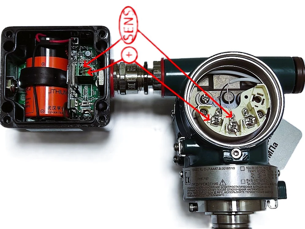
- Connect cable to ROSSMA switch at connector fig. 3. Pos 4. according to diagram Fig 4.
- Pass cable through switch cable gland (Fig 3. Pos 1.)
- Connect cable to pressure sensor according to diagram Fig 4.
- Tighten cable glands with required wrenches.
- Close pressure sensor top cover.
- Connect power connector fig 5. Pos 3. To mating part Fig 5.pos 2.
- Install top cover on ROSSMA switch (Fig 1. Pos 1,2,3,4)
Explosion-proof version: When installing in hazardous areas, follow PUE chapter 7.3 "Electrical installations in hazardous areas" and GOST 31610.7-2012.
¶ Interface Connection
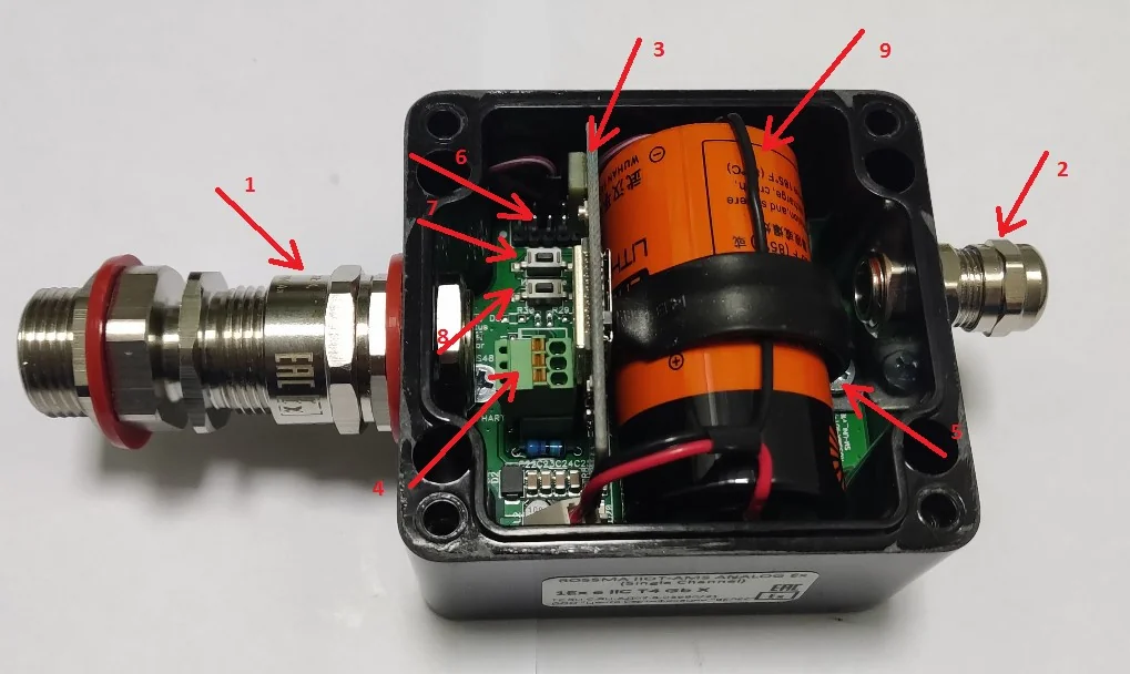
Fig.3 - Connector Description:
- Cable gland for pressure sensor connection
- Cable gland for additional antenna installation
- Communication module (NB IoT, optional - LoRa)
- Equipment/instruments connection connector (pressure sensors)
- Battery bracket mounting screw
- Programming connector
- "RESET" button
- "Measure and send" button
- Battery
¶ LED Indication
- "Status" LED blinks periodically – data transmission to server in progress.
- "Error" LED blinks once per second – communication module not detected or faulty.
- "Error" LED blinks in sequence three times – pause – three times – ROSSMA switch cannot register in network and obtain IP address.
- "Error" LED blinks in sequence five times – pause – five times – network server data transmission error.

¶ Battery Replacement
IMPORTANT: Battery replacement must be performed by qualified personnel. Repair and maintenance of meter-switch by consumer is not allowed!
¶ When is battery replacement needed?
Approximate battery life up to 10 years with data transmission once per day. Battery capacity of 14 Ah is designed for sending 40,000 data packets ± 10%.
If meter-switch malfunction is detected, check battery voltage. Device transmits voltage data with every connection.
¶ Replacement Instructions
- Turn off meter-switch (disconnect battery connector from board connector)
- Unscrew screw securing bracket inside housing
- Remove battery and bracket from housing
- Install new battery in housing
- Install bracket on battery and secure with screw
- Connect battery to power connector on board
- Check LED indication
CRITICAL: Use only non-rechargeable lithium-thionyl chloride (LiSOCl2) battery ER34615M/T manufactured by FANSO. Otherwise, manufacturer does not guarantee proper operation!
Battery technical parameters:
- Type: ER34615M/T (Fanso)
- Voltage: 3.6 V
- Capacity: 14 Ah
- Form factor: D
- Chemistry: LiSOCl₂ (lithium-thionyl chloride)
¶ Firmware
¶ Main Firmware (SM-UNI)
Version: 0.2.5 (19.12.2024) — ⬇️ Download
What's new in v0.2.5:
- Added communication interval query command (0x06 on port 3)
- Added HART sensor polling control (on/off)
- Added HART sensor polling control commands
📋 Version History
v0.2.3 (16.10.2024) — ⬇️ Download
- Added communication module firmware version data to BE packet
- Removed hard-coded region setting option
v0.2.2 (12.10.2024) — Archive data selection algorithm improvements, debug mode
v0.2.1 (08.10.2024) — Message send status check, sleep transition algorithm
v0.2 (07.10.2024) — Startup packet 0xBE, archive and log module v2, queue mechanism, command 0x41
v0.1 (20.04.2024) — First LoRaWAN version
¶ LoRaWAN Communication Module Firmware
Version: 0.5.0 (19.12.2024) — ⬇️ Download
What's new in v0.5.0:
- Changed main board notification packet format
- Improved data sending module to main board
📋 Version History
v0.4.3 (16.10.2024) — ⬇️ Download
- Main algorithm improvements
- Changed version request format
v0.4.2 (12.10.2024) — Reworked message sending algorithm, fixed duplicates
v0.4.1 (09.10.2024) — Version request command, fixed "0001" sending, new version system
¶ LR-HRT11 Firmware (Single Channel LoRaWAN)
Version: 1.6.0 (02.09.2024) — ⬇️ Download
What's new in v1.6.0:
- New build system
- Added LR-HRT11-V45Metran board support
- Added new version request format
For Metran/Yokogawa: ⬇️ Download lr-hrt11-metran-v1.6.0.hex
📋 Version History
v1.5 (02.03.2024)
- Added retry (2 attempts) for each HART sensor request
- Transferred analog value recalculation algorithm from LR-420x4
- Added universal sensor processing algorithm
v1.4 (09.11.2023)
- Added reed switch support (packet type 0xCE)
- Added short and long button press logic
v1.3.3 (31.03.2023) — Fixed packet length
How to update: Use ST-LINK programmer for flashing via SWD interface.
Configuration and programming go to